imrishabh18/rp2040-motor-controller
The circuit implements a powered USB interface with a W25Q16 flash memory chip, a RP2040 microcontroller, and AO3400A MOSFETs for switch control, enabling USB communication, memory storage, and device power management.
- Version
- 1.0.19
- License
- unset
- Stars
- 0
schematic/MotorOutputsSection.tsx
import { B4B_PH_CAD_MODEL } from "../imports/B4B_PH_K_S_LF__SN_";
import { motorTrace, schematicSections, schematicSheets } from "./config";

export const MotorOutputConnectors = () => (
	<connector
    cadModel={{
      ...B4B_PH_CAD_MODEL,
      // The routed footprint numbers pins left-to-right. The native OBJ
      // has terminals at x=0,2,4,6 on y=0, so center that row at the pads.
      pcbRotationOffset: 0,
      modelOriginPosition: { x: 3, y: 0, z: 0 },
      // Core anchors CAD at the footprint bounds, 0.05 mm below the pad row.
      positionOffset: { x: 0, y: 0.05, z: 0 },
    }}
    footprint={
      <footprint insertionDirection="from_above">
        {/* JST PH top entry: 2 mm pitch, 0.7–0.8 mm drills, 9.9 × 4.5 mm body.
            Manufacturer drawing: https://www.jst-mfg.com/product/pdf/eng/ePH.pdf */}
        <platedhole pcbX={-3} pcbY={0} portHints={["1"]}
          shape="circle" holeDiameter={0.75} outerDiameter={1.4} />
        <platedhole pcbX={-1} pcbY={0} portHints={["2"]}
          shape="pill" holeWidth={0.75} holeHeight={0.75} outerWidth={1.2} outerHeight={1.75} />
        <platedhole pcbX={1} pcbY={0} portHints={["3"]}
          shape="pill" holeWidth={0.75} holeHeight={0.75} outerWidth={1.2} outerHeight={1.75} />
        <platedhole pcbX={3} pcbY={0} portHints={["4"]}
          shape="pill" holeWidth={0.75} holeHeight={0.75} outerWidth={1.2} outerHeight={1.75} />
        <silkscreenrect pcbX={0} pcbY={0.55} width={9.9} height={4.5} strokeWidth={0.1} />
        <silkscreentext pcbX={-4} pcbY={-1} text="1" fontSize={0.5} />
        <silkscreentext pcbX={0} pcbY={3.25} text="JST PH" fontSize={0.5} />
        <courtyardrect pcbX={0} pcbY={0.55} width={10.9} height={5.5} />
      </footprint>
    }
    manufacturerPartNumber="B4B-PH-K-S(LF)(SN)"
    supplierPartNumbers={{ jlcpcb: ["C131334"] }}
    pinLabels={{pin1:["A_PLUS"],pin2:["A_MINUS"],pin3:["B_PLUS"],pin4:["B_MINUS"]}}
		name="J1"
		pcbPinLabels={{
			pin1: "A+",
			pin2: "A-",
			pin3: "B+",
			pin4: "B-",
		}}
		pcbX={22.625}
		pcbY={3.25}
		pcbRotation={90}
		schX={9}
		schY={-1.5}
		schPinArrangement={{
			leftSide: { pins: [1, 2, 3, 4], direction: "top-to-bottom" },
		}}
		schSheetName={schematicSheets.motorDriver}
		schSectionName={schematicSections.motorOutputs}
	/>
);

export const MotorOutputTraces = () => (
	<>
		{/* Reserve room for the wider motor routes before the remaining signals. */}
		<trace
			name="MOTOR_A_PLUS"
			from=".DRIVER > .AOUT1"
			to=".J1 > .pin1"
			schDisplayLabel="A+"
			{...motorTrace}
		/>
		<trace
			name="MOTOR_A_MINUS"
			from=".DRIVER > .AOUT2"
			to=".J1 > .pin2"
			schDisplayLabel="A-"
			{...motorTrace}

		/>
		<trace
			name="MOTOR_B_PLUS"
			from=".DRIVER > .BOUT1"
			to=".J1 > .pin3"
			schDisplayLabel="B+"
			{...motorTrace}
		/>
		<trace
			name="MOTOR_B_MINUS"
			from=".DRIVER > .BOUT2"
			to=".J1 > .pin4"
			schDisplayLabel="B-"
			{...motorTrace}
		/>
	</>
);
Related Packages
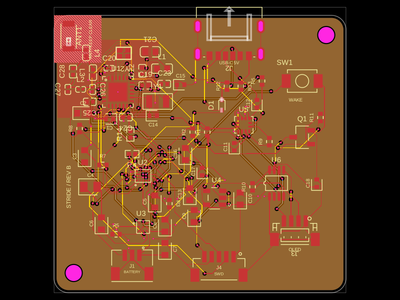 More from this authorimrishabh18/pedometerThis code defines and assembles a simple radio receiver hardware circuit using specific imported capacitors, inductors, RF connectors, and oscillator components with precise footprints and schematic attributes.
 Similar packagemohan-bee/esp32-c3This hardware design integrates an ESP32-C3 microcontroller, a USB-C connector, a power management IC (AP2112-3.3V regulator), a USB-to-Serial converter (CH340C), several resistors, capacitors, and user-accessible headers to facilitate USB communication, power regulation, and general I/O interfacing.
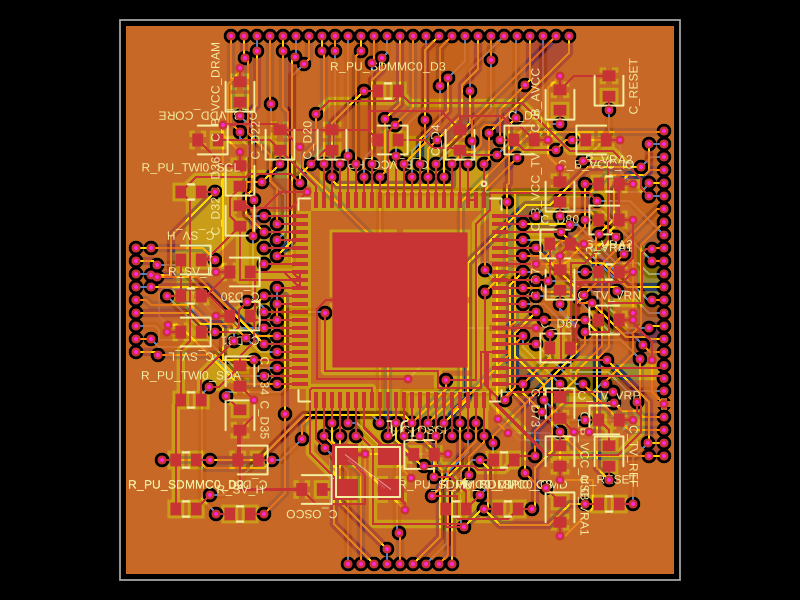 Discover something newastra/f1c100sThe code defines the physical pin layout, labels, and footprint for the F1C100S system-on-chip (SoC) component used in electronic devices.