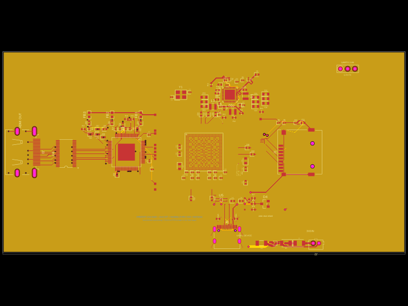
README.md
## Larger bulk capacitor footprints

All seven rail bulk capacitors now use 0805 footprints and selected 25 V Murata parts. The three 10 µF reference filters use the same larger package. These ten parts are on the bottom side to preserve the short top-side pin decouplers. The module now requires two-sided assembly. See [part selection and DC-bias data](docs/bulk-capacitors.md).

## Direct decoupling connections

All 15 dedicated `C_D<pin>` capacitors connect their supply pad directly to the matching `U1.pin<pin>` through an explicit two-port source trace. Their ground pad remains on GND; bulk capacitors remain rail-connected. The stored-route generator reserves each assigned capacitor-to-pin branch before constructing shared rail trees. All five layout profiles were regenerated and checked. Dedicated supply pads are within 3.4 mm of their assigned pin, branches are at most 5 mm and remain on top without vias, and each ground pad has a GND via within 1.3 mm. These are project layout limits, not datasheet specifications. On the native layout the longest branch is 3.15 mm, down from 9.46 mm. The clock assembly is rotated and moved to avoid crossing clock routes while providing space for pin 50 decoupling.

`check-decoupling-targets.ts` checks physical pad-to-pad branches, and the module tests check exact rendered source-port pairs as well as copper preservation and DRC. These checks do not treat same-net reachability as a substitute for an assigned branch.

## Selective external connections

Version 0.11.0 creates exit pads and external fanout only for truthy entries in `connections`. Omitting `connections` creates no external breakouts. Processor pins and internal support circuitry are preserved, including decoupling, clock, reset, references and pull-ups.

```tsx
<F1C100SModule name="SOC" connections={{
  GND: "net.GND",
  VCC_IO: "net.V3V3",
  UART0_TX: ".DEBUG > .pin1",
}} />
```

The selected layout profile still determines exit positions. Stored paths are re-rooted at internal ports when an exit is omitted; branches needed only by that exit are not loaded. A former plated exit used as an internal junction is replaced by a via where needed to preserve its layer transition. No new module routing solver is used.

To show all exits, explicitly connect all names from `EXTERNAL_NETS`; `ProfilePreview` does this. `getF1C100SCircuitJson` continues to return the complete reference layout. Run `bun test` for both complete-layout and selective-breakout regression checks.

This source is also included in the companion F1C100S dev-board project.

---

# F1C100S for tscircuit

An F1C100S module with five pre-routed layout profiles, supply decoupling, reference circuits, a 24 MHz crystal, reset support, and bus pull-ups. Use it on a four-layer PCB with `tscircuit@0.0.2495`.

## Install

```sh
tsci add astra/f1c100s
```

```tsx
import { F1C100SModule } from "@tsci/astra.f1c100s"

export default () => (
  <board width={28} height={28} layers={4} minTraceWidth={0.12}
    minViaPadDiameter={0.45} minViaHoleDiameter={0.2}>
    <F1C100SModule name="SOC" layoutProfile="lcd_top_storage_right" />
  </board>
)
```

## Choose a layout profile

| `layoutProfile` | RGB666 LCD exit | SPI0 and SDMMC0 exits |
| --- | --- | --- |
| `native` (default) | Nearby package edges | Nearby package edges |
| `lcd_top_storage_right` | Top | Right |
| `lcd_right_storage_bottom` | Right | Bottom |
| `lcd_top_storage_bottom` | Top | Bottom |
| `lcd_right_storage_left` | Right | Left |

Directions are relative to the module. `pcbRotation={90}` rotates the complete module, including its exits. All profiles expose the same electrical connections. Configure the processor's pin mux in firmware for RGB666, SPI0, SDMMC0, UART0, and TWI0.

## Place and connect

Give each instance a unique `name`. Use `pcbX`, `pcbY`, and `pcbRotation` for PCB placement, and `schX` and `schY` to position its schematic.

```tsx
<F1C100SModule
  name="SOC"
  layoutProfile="lcd_right_storage_bottom"
  pcbX={10}
  pcbY={0}
  connections={{
    UART0_TX: ".DEBUG > .pin1",
    UART0_RX: ".DEBUG > .pin2",
    GND: "net.GND",
    VCC_IO: "net.V3V3",
  }}
/>
```

`connections` maps terminal names to parent component selectors or named nets. The names and `.pin1` selectors also apply to the plated test points. To use an explicit parent trace:

```tsx
<trace from=".SOC .SPI0_CLK > .pin1" to=".FLASH > .CLK" />
```

All 71 exits are bare plated-hole test points, with 0.45 mm copper diameter and 0.20 mm drill. They connect top, inner1, inner2, and bottom copper, so carrier traces can reach any exit on any of the four layers. The holes are exposed for probing and do not require fitted components. Reserve a 28 × 28 mm square and mount the module on the top side. The supply/reference pad of each decoupling capacitor faces its chip pin; the crystal load capacitors face the crystal. The processor, 22 small capacitors, all 13 resistors, and the crystal are on the top layer; ten 0805 capacitors are on the bottom layer; the breakout test points pass through the board. Routing uses all four copper layers, with no layer reserved as a solid power or ground plane. Use fabrication rules compatible with 0.12 mm traces, 0.10 mm clearance, and through-vias with 0.45 mm copper diameter and 0.20 mm drill.

## Arrange the schematic

Set `schematicLayout="custom"` on the module, then import the schematic boxes you want to place. These components represent the existing processor; they add no PCB parts or routes. Use each box once to show all processor pins.

| Component | Processor pins |
| --- | --- |
| `F1C100SLcdSchematicBox` | RGB666 data and timing |
| `F1C100SStorageSchematicBox` | SPI0 and SDMMC0 |
| `F1C100SGpioSchematicBox` | UART0, TWI0, PE2–PE10 |
| `F1C100SAudioSchematicBox` | Audio inputs, outputs, and references |
| `F1C100SVideoTouchSchematicBox` | Video, touch, and ADC |
| `F1C100SSystemSchematicBox` | Clock, reset, USB, and SDRAM reference |
| `F1C100SPowerSchematicBox` | Supply and ground pins |

Each box requires `moduleName`, matching the module's `name`. Place it with `schX` and `schY`; assign `schSectionName` to a `<schematicsection />`, and use a `<schematicsheet>` parent or `schSheetName` to select its sheet. Optional `name`, `width`, and `height` override its defaults.

The module keeps its included capacitors, resistors, crystal, and their connections. In custom mode, its `schX`, `schY`, and `schSheetName` place this compact support group. You choose where the processor boxes and your peripheral circuits belong. The module does not create schematic sheets.

This complete example uses the same two A4 sheets as the preview:

```tsx
import {
  F1C100SModule,
  F1C100SLcdSchematicBox,
  F1C100SStorageSchematicBox,
  F1C100SGpioSchematicBox,
  F1C100SAudioSchematicBox,
  F1C100SVideoTouchSchematicBox,
  F1C100SSystemSchematicBox,
  F1C100SPowerSchematicBox,
} from "@tsci/astra.f1c100s"

export default () => (
  <board width={28} height={28} layers={4}
    minTraceWidth={0.12} minViaPadDiameter={0.45} minViaHoleDiameter={0.2}
    schLayout={{layoutMode: "relative"}}>
    <schematicsheet name="interfaces" displayName="F1C100S — interfaces" sheetSize="A4">
      <schematicsection name="lcd" displayName="RGB666 LCD" />
      <schematicsection name="storage" displayName="SPI / SDMMC" />
      <schematicsection name="gpio" displayName="UART / I²C / GPIO" />
      <schematicsection name="audio" displayName="Audio" />
      <schematicsection name="video" displayName="Video / touch" />
      <schematicsection name="system" displayName="Clock / reset / USB" />
      <F1C100SLcdSchematicBox moduleName="SOC" schX={-10} schY={5} schSectionName="lcd" />
      <F1C100SStorageSchematicBox moduleName="SOC" schX={-1} schY={5} schSectionName="storage" />
      <F1C100SGpioSchematicBox moduleName="SOC" schX={8} schY={5} schSectionName="gpio" />
      <F1C100SAudioSchematicBox moduleName="SOC" schX={-10} schY={-4} schSectionName="audio" />
      <F1C100SVideoTouchSchematicBox moduleName="SOC" schX={-1} schY={-4} schSectionName="video" />
      <F1C100SSystemSchematicBox moduleName="SOC" schX={8} schY={-4} schSectionName="system" />
    </schematicsheet>
    <schematicsheet name="power" displayName="F1C100S — power and support" sheetSize="A4">
      <F1C100SModule name="SOC" layoutProfile="lcd_top_storage_right" schematicLayout="custom" />
      <schematicsection name="power_pins" displayName="Power" />
      <F1C100SPowerSchematicBox moduleName="SOC" schX={-11} schY={6.5} schSectionName="power_pins" />
    </schematicsheet>
  </board>
)

```

Omit `schematicLayout="custom"` to use the module's default arrangement, including all seven boxes. Do not add another set of boxes in that mode. With multiple processors, give each module a unique name and organize their support groups and boxes on your chosen sheets.

## Terminal names

| Interface | Names accepted by `connections` |
| --- | --- |
| LCD data | `LCD_D2`–`LCD_D7`, `LCD_D10`–`LCD_D15`, `LCD_D18`–`LCD_D23` |
| LCD timing | `LCD_CLK`, `LCD_DE`, `LCD_HSYNC`, `LCD_VSYNC` |
| SPI0 | `SPI0_CLK`, `SPI0_CS`, `SPI0_MISO`, `SPI0_MOSI` |
| SDMMC0 | `SDMMC0_CLK`, `SDMMC0_CMD`, `SDMMC0_D0`–`SDMMC0_D3` |
| UART / I²C | `UART0_TX`, `UART0_RX`, `TWI0_SDA`, `TWI0_SCL` |
| GPIO | `PE2`–`PE10` |
| USB / reset | `USB_DM`, `USB_DP`, `RESET` |
| Audio | `HPL`, `HPR`, `HPCOM`, `FMINL`, `FMINR`, `LINEIN`, `MICIN` |
| Video / touch / ADC | `TVOUT`, `TVIN0`, `TVIN1`, `TPX1`, `TPX2`, `TPY1`, `TPY2`, `LRADC0` |
| Power | `VDD_CORE`, `VCC_DRAM`, `VCC_IO`, `VCC_USB`, `AVCC`, `VCC_HP`, `VCC_TV`, `GND` |

Connect each supply rail to the appropriate external supply. The module includes the local processor support components listed below. Add regulators, boot storage (SPI flash or SD card), and the connectors and application circuits needed by your carrier. Keep the power domains separate and follow the [F1C100S datasheet](https://linux-sunxi.org/images/b/ba/F1C100s_Datasheet_V1.0.pdf) for supply voltages, sequencing, and peripheral requirements.

## Included support components

| Circuit | Included parts |
| --- | --- |
| Supply decoupling | 15 × 100 nF, one per supply pin; six × 10 µF and one × 1 µF bulk capacitor |
| 24 MHz clock | Abracon `ABM8-24.000MHZ-12-B1U-T`, with two 18 pF C0G Murata `GRM1555C1H180JA01D` load capacitors |
| Reset | 47 kΩ pull-up to `VCC_IO` and 100 nF to ground |
| SDRAM reference | Two 2 kΩ resistors and two 100 nF capacitors |
| VRA1 / VRA2 references | Each has 200 kΩ and 1 µF to ground |
| TV references | 10 µF from each reference to ground, plus 10 µF between `TV_VRP` and `TV_VRN` |
| SDMMC0 | 47 kΩ pull-ups on CMD and D0–D3 to `VCC_IO` |
| SPI0 | 10 kΩ pull-up on CS to `VCC_IO` |
| TWI0 / I²C | 4.7 kΩ pull-ups on SDA and SCL to `VCC_IO` |

The oscillator is internal to the module: `HOSCI` and `HOSCO` are not carrier terminals. Its traces stay on top without vias. The 18 pF loads target the crystal's 12 pF load capacitance assuming 3 pF of pin and PCB stray capacitance; tune the fitted values if oscillator measurements require it.

Account for the included pull-ups when connecting storage or an I²C bus. Choose any additional I²C pull-ups for your bus capacitance and speed. Peripheral-specific components, such as USB protection, audio coupling and filtering, video termination, and display power circuitry, belong in the carrier's application circuit.

## Add copper pours

The previews add GND pours on all four layers, with 0.15 mm clearance, 0.30 mm board-edge clearance, and thermal reliefs. Add pours to your carrier board and connect the module's ground to the same net:

```tsx
<board width={28} height={28} layers={4}
  minTraceWidth={0.12} minViaPadDiameter={0.45} minViaHoleDiameter={0.2}>
  <net name="GND" />
  <F1C100SModule name="SOC" layoutProfile="lcd_top_storage_right"
    connections={{ GND: "net.GND" }} />
  {(["top", "inner1", "inner2", "bottom"] as const).map(layer => (
    <copperpour {...{ key: layer }} layer={layer} connectsTo="net.GND"
      clearance={0.15} boardEdgeMargin={0.3}
      useThermalReliefs coveredWithSolderMask />
  ))}
</board>
```

The fills follow the existing traces and clear other nets. Choose the layers and pour outlines for your carrier; importing the module does not add board-wide pours.