imrishabh18/rp2040-motor-controller
The circuit implements a powered USB interface with a W25Q16 flash memory chip, a RP2040 microcontroller, and AO3400A MOSFETs for switch control, enabling USB communication, memory storage, and device power management.
- Version
- 1.0.19
- License
- unset
- Stars
- 0
reports/schematic-cleanup.md
# Schematic cleanup — 2026-09-14

Ran `bunx --package @tscircuit/cli@latest tsci check schematic-placement` (tsci reported version 0.0.2547), following the latest CLI netlist check.

Reorganized bypass capacitors into compact rail banks, aligned LED and BOOT/RUN branches, separated SWD test points, corrected vertical rail components, and replaced colliding automatic section headings with explicit headings. All six rendered sheets were visually reviewed. The PCB elements are identical to the encoder-only-bottom revision: all 19 PCB element types compare exactly.

The latest analysis reports no text collisions, component overlaps, component/net-label collisions, capacitor grouping issues, two-pin orientation issues or overly wide generic schematic boxes. All elements pass the sheet-boundary regression.

Remaining heuristic suggestions: 42 pin-padding notices, 3 trace simplification suggestions and 1 diode/resistor orientation suggestion. They remain visible; none were suppressed. Symbol padding preserves internal pin-label readability. The regulator receives contradictory upward and downward move suggestions from different wires; the diode and enable resistor share a clear upward supply rail.

Validation: zero embedded errors, zero independent routing errors, zero tsci check errors, no Gerber shorts on all four layers. One GND declaration and 29 required ground terminals verified. 12 circuit tests (1049 assertions) and 16 firmware tests passed. PCB placement has zero errors and warnings. The connected dev server also displayed zero PCB errors and the updated schematic.
Related Packages
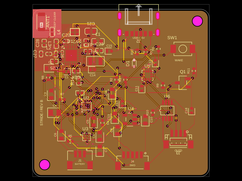 More from this authorimrishabh18/pedometerThis code defines and assembles a simple radio receiver hardware circuit using specific imported capacitors, inductors, RF connectors, and oscillator components with precise footprints and schematic attributes.
 Similar packagemohan-bee/esp32-c3This hardware design integrates an ESP32-C3 microcontroller, a USB-C connector, a power management IC (AP2112-3.3V regulator), a USB-to-Serial converter (CH340C), several resistors, capacitors, and user-accessible headers to facilitate USB communication, power regulation, and general I/O interfacing.
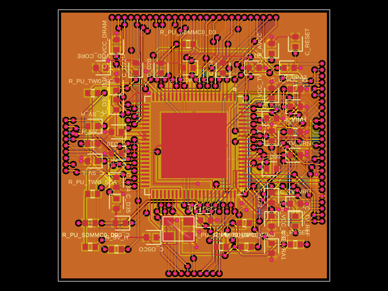 Discover something newastra/f1c100sThe code defines the physical pin layout, labels, and footprint for the F1C100S system-on-chip (SoC) component used in electronic devices.