imrishabh18/rp2040-motor-controller
The circuit implements a powered USB interface with a W25Q16 flash memory chip, a RP2040 microcontroller, and AO3400A MOSFETs for switch control, enabling USB communication, memory storage, and device power management.
- Version
- 1.0.19
- License
- unset
- Stars
- 0
mechanical/README.md
# NEMA 17 rear-mounted controller

The outline follows the PD-Stepper V1.1 Gerber perimeter from joshr120/PD-Stepper, commit `3c40073a0ec51653f6ea48c70f365bd7f9f3bdcc`:
https://github.com/joshr120/PD-Stepper/tree/3c40073a0ec51653f6ea48c70f365bd7f9f3bdcc/PCB

- Overall outline: approximately 42.30 × 42.32 mm.
- Four mounting centers: (±15.5, ±15.5) mm, giving a 31 × 31 mm square.
- Mounting drill: 3.3 mm. Grounded 5.6 mm copper rings; placement reserves a 6.5 mm screw-head clearance circle.
- The perimeter's 3 mm corner transitions are approximated with 12 straight segments per 45-degree arc (maximum deviation approximately 0.002 mm).
- Only the AS5600 at (0, 0) is assembled on the bottom, facing the motor. Every other component is on top, including the buzzer at (15, 6) and motor capacitor at (−18, −1.5) mm. Use insulated spacers; do not rest solder joints directly on the metal motor end plate.
- PD-Stepper includes a 2.5 mm heat-spreader model and only the central encoder on its underside. Our spacer must clear the particular motor’s rear shaft/bearing boss, the encoder (approximately 1.75 mm high), the magnet and protruding connector leads. Choose its thickness from that mechanical stack and the required magnetic sensing gap; the reference thickness is not a verified fit for this board. Screw length depends on motor length and the spacer/cover stack.
- The reference cover/heatspreader is not interchangeable: this design has different components, connector openings and thermal-contact positions.
- Motor connector: four-pin JST PH, 2 mm pitch, A+, A−, B+, B−. This requires a matching cable in place of the original screw-terminal connection.

NEMA 17 describes the motor frame; check the actual motor's rear fasteners before ordering boards. The reference uses replacement motor tie screws. The PCB measures nearby driver-board temperature, not winding temperature.

The sampled perimeter is adapted from the PD-Stepper V1.1 Gerbers. The upstream GPL-3.0 license is included as `PD-Stepper-LICENSE`. This repository contains the modified outline source.

## Encoder magnet

The board origin must align with the motor shaft. Fit a diametrically magnetized on-axis magnet to an accessible rear shaft, facing the AS5600. The exact magnet, holder and axial gap depend on the motor, which has not been specified. Start from the sensor manufacturer’s magnet guidance and adjust until the firmware reports a valid field through a full revolution. Ensure the magnet cannot strike the chip and keep the buzzer opening clear. This is single-turn position sensing; there is no shaft pass-through hole at the board centre.
Related Packages
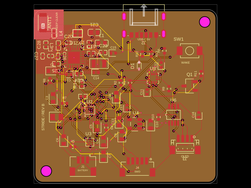 More from this authorimrishabh18/pedometerThis code defines and assembles a simple radio receiver hardware circuit using specific imported capacitors, inductors, RF connectors, and oscillator components with precise footprints and schematic attributes.
 Similar packagemohan-bee/esp32-c3This hardware design integrates an ESP32-C3 microcontroller, a USB-C connector, a power management IC (AP2112-3.3V regulator), a USB-to-Serial converter (CH340C), several resistors, capacitors, and user-accessible headers to facilitate USB communication, power regulation, and general I/O interfacing.
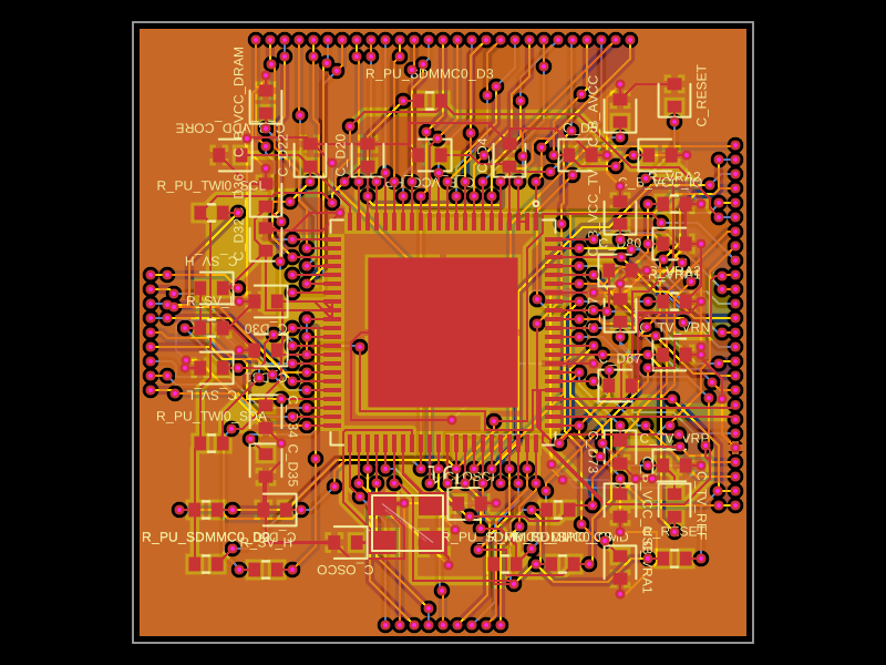 Discover something newastra/f1c100sThe code defines the physical pin layout, labels, and footprint for the F1C100S system-on-chip (SoC) component used in electronic devices.