MustafaMulla29/stride-pedometer
This code defines schematic symbols and 3D footprints for various hardware components such as antennas, sensors, regulators, and connectors used in electronic circuit design.
- Version
- 1.0.4
- License
- unset
- Stars
- 0
docs/off-board-parts.csv
Item,Quantity,Specification,Assembly
Battery,1,"Protected rechargeable 1S LiPo; 100 mAh nominal; 4.2 V charge; accepts 20 mA; size must be checked against enclosure",Wire to J2 PACK_P/GND
Battery NTC,1,"10 kOhm at 25 C; provisional B3435; thermally attached to cell; verify charger temperature thresholds",Wire to J2 TS/GND
Display,1,"Wisevision X091-2832TSWFG02-H14; LCSC C18723017; bare 14-pin OLED glass",Solder flex to DS1 after PCBA reflow
Display spacer,1,"Insulating nonconductive support; height and flex fold validated with actual glass",Mechanical assembly
Charging dock,1,"Regulated 5 V source and two spring contacts; correct polarity; at least 100 mA capability",Contacts J1
Programming probe,1,"TI-supported SWD probe with 3 V target logic/reference",TP1-TP5
Enclosure,1,"Nonconductive housing; antenna corner clear of battery foil and metal; dimensions after display fit check",Mechanical assembly
Related Packages
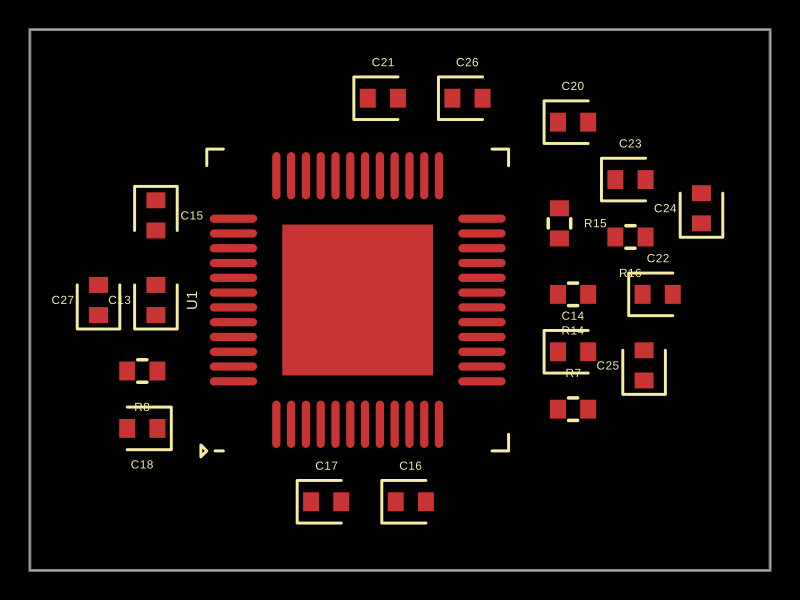 More from this authorMustafaMulla29/ti-chipThis code models a hardware circuit for a motor driver using a DRV83053QPHPQ1 integrated circuit, with power supply bypass capacitors, charge-pump capacitors, resistors, and filters, representing the physical connections and key components in a motor control power stage.
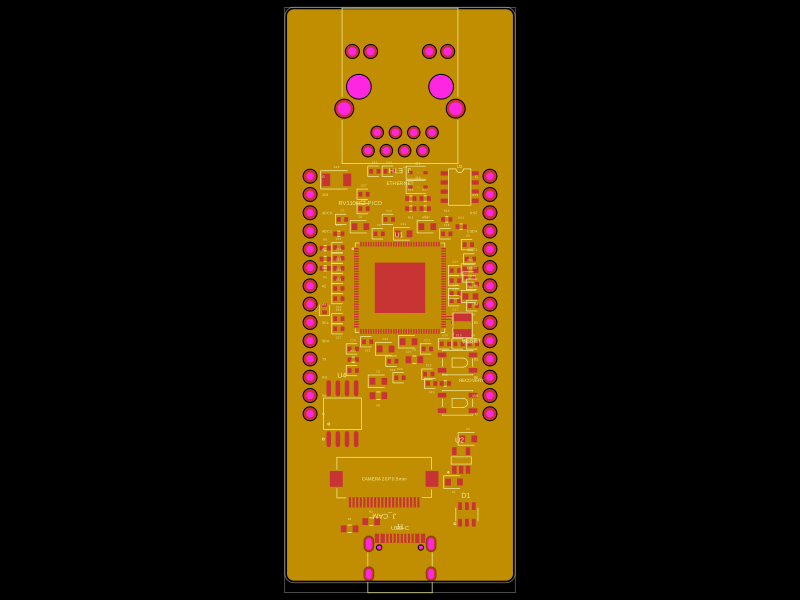 Similar packagemohan-bee/RV1106G2This code defines a detailed hardware schematic with schematic symbols, footprints, and 3D models for various electronic components including microcontrollers, voltage regulators, connectors, and passive parts, designed for PCB layout and routing.
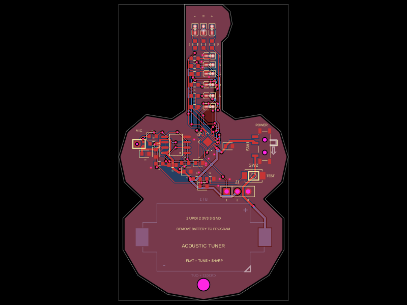 Discover something newgokul/acoustic-guitar-tunerThis code defines the physical pin configuration and footprint layouts for the ATtiny1616 microcontroller and a matching tactile switch component, including their key hardware connection points, dimensions, and 3D models.